
This project started out as an exercise to build a 6m receiver to monitor my own WSPR transmissions. The design did not need to be particularly complex nor did the performance need to be spectacular. I decided Build a converter for my trusty (but a bit drifty) Yaesu FRG-7700 receiver. IF to be 18-20MHz for the 6m band 50-52MHz.
I decided that the design should be as simple and should use a minimum number of components.. These components should, if possible, be available from GQRP Sales. The simple design should use a battery as a power source to minimise the possibility of noise and complexity and would allow portable or remote use without AC power.
Fig 1. Layout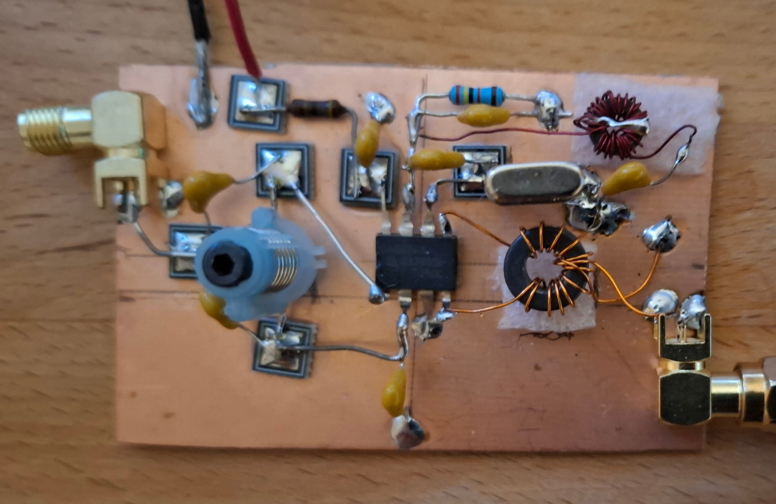
After some deliberation I decided to base the design on the ubiquitous NE602 as shown in fig.3. Yes, it is an old device but it has the advantage of a lot of tribal knowledge, is easily available and cheap! The circuit chosen is a mixture of those found on the data sheet2. The oscillator is a 3rd overtone as shown on page 6, fig. 6 (a). The input circuit is as Page 5, fig. 4 (a), the output circuit is as page 5, fig. 5 (d) but untuned, i.e., no capacitor. The optional additional emitter resistor, (22k or 24k) was added to improve oscillator reliability at the 3rd overtone. Power from a 6V SLA battery was via a 47R resistor with a 100nF decoupling capacitor at the feed point. If a higher voltage supply is used a Zener diode and higher value resistor is definitely necessary, see table 1.
L1 is a very old blue former 6.5 turn inductor with a vhf ferrite core that was found in my junk box, believed to be a Toko S18 approximately 0.3uH.
L2 (for a 32MHz crystal) is 26 turns on a T25 toroid with an Al value of approximately 2.5 giving an inductance of approximately 1.7 to 1.9uH.
L3 is wound on an FT37-43 toroid with 12 turns primary, 2 turns secondary. Note that this inductor will need tailoring to the IF used.
Table 1 Power supply values
Voltage R1 Approx current
6v -7v 47R No zener 2.5mA
9v 680R 6v zener 4.5mA
12v – 14v 1k2 6v zener 5mA
The results obtained were in line with expectation using a simple scratch dipole tuned with a Nano VNA, aligned North/South fed from 2m of coax and hung in the shack with blue tack.. Under normal conditions I get regular reception of WSPR signals from Harlow area about 35Km away with good S/N using WSJT-X. I have yet to experience an “opening” but am confident that the converter works well.
The build used me squares mounted on a small piece of single sided pcb as a ground plane as shown in fig.1. Note that L2 nd L3 are spaced off the pcb surface by small pieces of 4mm thick expanded polystyrene super glued to the pcb in order to avoid capacative effects as shown in Fig.2.
Fig 2 L2 Mount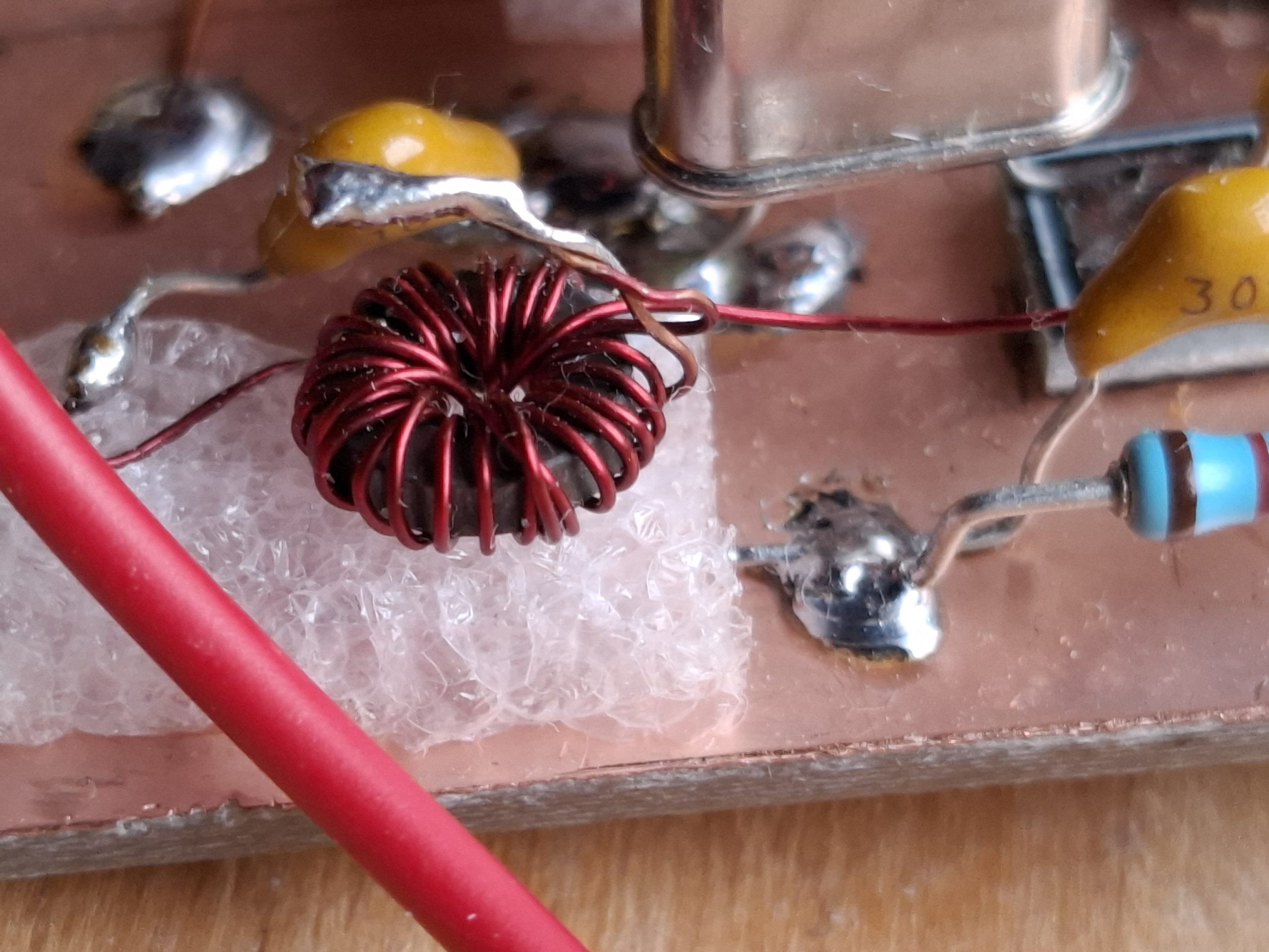
Fig 3 – Schematic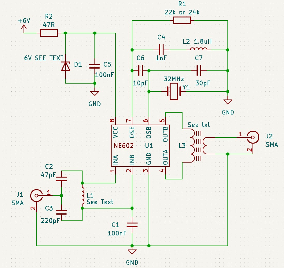
Whilst researching this design I came across a number of references that gave good advice but also some had serious errors in their proposed design. In particular reference 3 has Fig 7 showing the inductor L2 and capacitor C4 connected to the base of the NE602. This does not work, the connection should be to the emitter. There are other errors in this document as well.
My thanks to the GQRP forum for help in getting the overtone oscillator to work reliably.
References:
1) NE602 Data Sheet: https://www.nxp.com/docs/en/data-sheet/SA602A.pdf
2) SA612A: https://www.nxp.com/docs/en/data-sheet/SA612A.pdf
3) NE602 Application note: https://www.lb3hc.net/wp-content/uploads/2019/12/UsingTheNe602.pdf