
In this post I will show you how to make a very accurate thermostat controlled by a Raspberry Pi Pico. This project started because I needed an accurate controller for my propagator. Some seeds, e.g. chillis and tomatoes, need heat to germinate and also need to be started early in the year when it is cold. My propagator is a Stewart model with no proper temperature control running from mains power (230v AC), consuming about 22 watts. I also have a smaller one using 15 watts. The propagator can also be used to prove/rise bread dough when set to 30+C.
The Raspberry Pi Pico is a relatively new product (Jan. 2021) and I determined to learn how to use it as soon as I heard of it. The Pico is ideally suited to this type of task as it has a rich set of input/output pins, a fast dual core ARM processor, a lot of memory, both flash and RAM and can be programmed using Python (my preference) or C++ (for the clever ones!) Full details of the Pico can be found here.
The Pico does have various serial communications capabilities (I2C etc.) but no WiFi or Ethernet interfaces. This does not matter to me in this project as I do not need data logging or sms/email alarms for such a simple task. WiFi connectivity could be added later if required using one of the ESP8266 devices.
My specification:
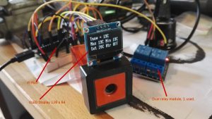
- Oled display 128 x 64 (because I had one lying around) to show temperature to maintain (Tset), Max and Min temperatures.
- One button to set the required temperature
- One relay output capable of safely switching mains power (BE CAREFUL!!)
- DS18B20 one wire temperature sensor, this is capable of measuring temperature VERY accurately.
- Powered by USB adapter (could use batteries but no point).
- Take readings at 15 minute intervals (customisable, see later)
Parts required:
- 1 x Raspberry Pi Pico
- 1 x Oled Display 128 x 32 or 128 x 64 for larger text (see later)
- 1 x 5v Relay module (diagram shows 2 relay module, 1 used)
- 1 x DS18B20 thermometer device, either stand alone as per diagram or long
- leaded for remote sensing
- 1 x normally open push button
- 1 x 4.7k resistor, 1/4 watt
- 1 x breadboard, should fit on small size
- 18 x hookup wires, various lengths, 10 x male to male, 8 x male to female for Oled and relay module
- USB power supply, 250mA should be more than enough or use PC USB outlet for testing and setup.
Breadboard wiring diagram, click for larger image
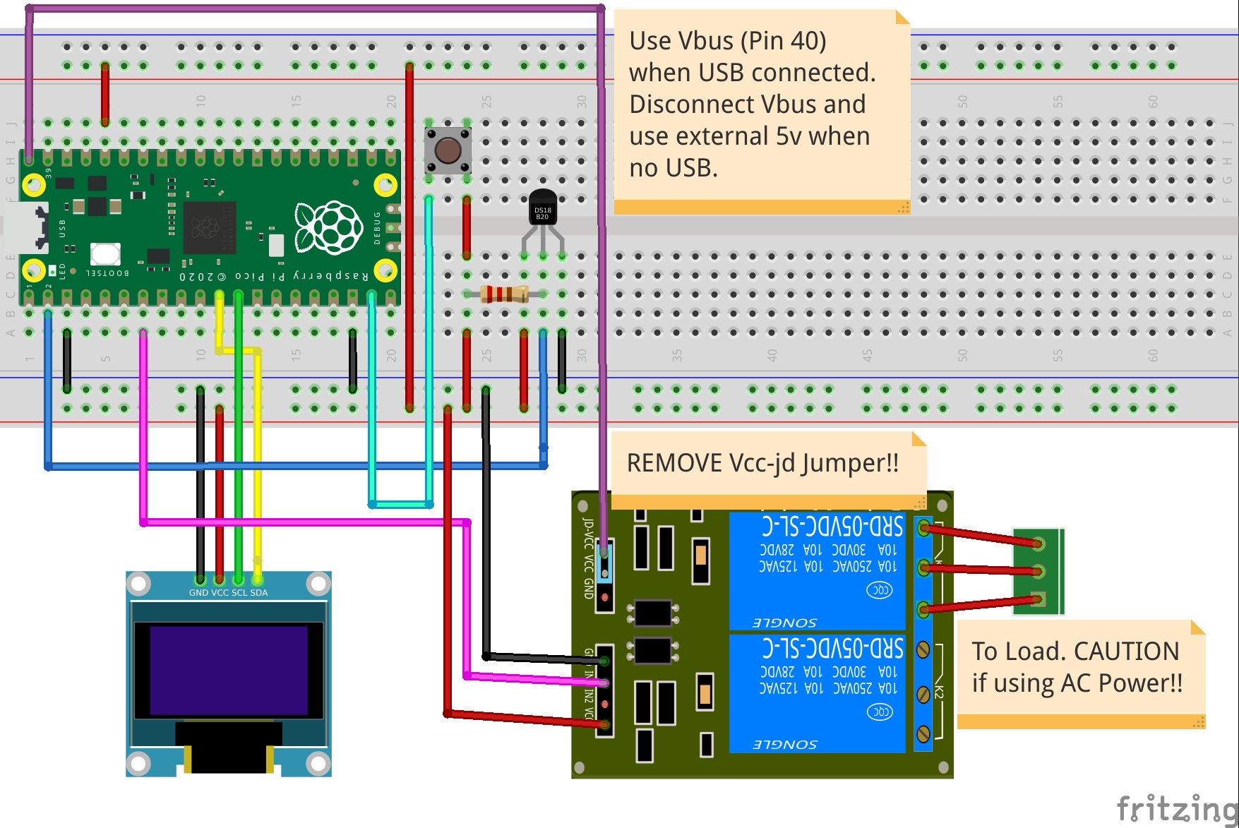
Notes: make sure that you remove the Vcc to Vcc-JD jumper on the relay module. If you do not, you will almost certainly damage the PiPico or the module or both! The hookup diagram above assumes that you are using USB power. If you are using an external power supply, make sure that you connect it to pin 39 (Vsys) and that it can supply 5v (do NOT exceed 5.5v!) at 250mA or more. Do not connect any load to the relay until you have a proven working hookup.
WHEN SWITCHING AC POWER, MAKE SURE THAT ALL CONNECTIONS ARE WELL INSULATED AND NOT ACCESSIBLE.
The software:
Before powering the hookup, check your wiring carefully, also read the getting started guide for the Pico carefully making sure that you have installed Thonny or a similar IDE and that the Pico is prepared for use with MicroPython.
The software is written in MicroPython, is relatively simple, and can be downloaded from HERE. Remember to rename the file to type .py as it is downloaded as type .pytxt. Check that the python indentation has been kept, if it is not you will get syntax errors.
You will also need to install drivers (import packages) for the SSD1306 and onewire. Use the Thonny package manager to do this (Tools/manage packages).
Customisation:
Temperature range:
When examining the programme you will notice that the temperature range setting (lines 48 and 49) maximum and minimum temperature variables can be changed to a range to suit your application. The initial value of the thermostat is 20C. The set temperature is adjusted by 1C for each push of the button between 10C and 30C. The push button uses an interrupt to read changes. The debounce time is set to 0.15s in line 55, adjust this to suit your button if necessary. Originally the code used a separate thread to read the button but this proved unreliable and the interpreter seemed to be unstable so threads were discarded.
There is also a hysteresis value, i.e. the amount by which the temperature must change before the relay is switched. This is set in line 10, default is +/-0.5C.
Reading frequency:
Readings are taken at 6 second intervals by default, line 88. change this to a value in seconds to suit your application. With high thermal mass equipment such as a propagator it is unlikely that the temperature will change rapidly so 1 minute or 15 minutes may be more appropriate. Experiment!
The Display:
You will also see that the OLED is set to a size 128 x 32, not 128 x 64 as used. This is because the text size at 128 x 64 is too small to be read easily and the MicroPython driver package for the SSD1306 does accommodate different font sizes. If you use a 128 x 32 OLED, you will get the smaller font with no adjustment of the code.
And finally:
I now need to package the unit in a damp-proof insulated box to make it safe and permanent.
I hope that you have enjoyed reading this article and that it has given you ideas to use in Pi Pico in projects of your own.
Regards to all, stay safe, XilAdmin.